
 Product
 Brand
Brand Articles
 Tools
Tools
What are Comparators?
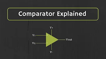
Comparator Explained
Catalog
Ⅰ Principle
The comparator is a circuit that compares an analog voltage signal with a reference voltage. The two inputs of the comparator are analog signals, and the output is a binary signal 0 or 1. When the difference of the input voltage increases or decreases and the sign of the positive and negative remains unchanged, the output remains constant.
The comparator can be used as a 1-bit analog-to-digital converter (ADC). The operational amplifier can be used as a comparator in principle when no negative feedback is added, but because the open-loop gain of the operational amplifier is very high, it can only process signals with a very small input differential voltage. Moreover, in general, the delay time of the operational amplifier is long, which cannot meet the actual demand. The comparator can be adjusted to provide a very small time delay, but its frequency response characteristics will be limited. To avoid output oscillation, many comparators also have internal hysteresis circuits. The threshold of the comparator is fixed, some have only one threshold, and some have two thresholds.
Ⅱ Performance
Hysteresis voltage: The voltage between the two input terminals of the comparator will change its output state when it crosses zero. Because the input terminal is often superimposed with small fluctuation voltage, The differential mode voltage generated by these fluctuations will cause the comparator output to change continuously. In order to avoid output oscillation, new comparators usually have a hysteresis voltage of several mV. The existence of the hysteresis voltage makes the switching points of the comparator become two: one is used to detect the rising voltage, the other is used to detect the falling voltage, the difference of the voltage threshold (VTRIP) is equal to the hysteresis voltage (VHYST). The offset voltage of the hysteresis comparator is the average value of TRIP and VTRIP-. The input voltage switching point of the comparator without hysteresis is the input offset voltage, not the zero voltage of the ideal comparator. The offset voltage generally varies with temperature and power supply voltage. The power supply rejection ratio is usually used to express the influence of power supply voltage changes on the offset voltage.
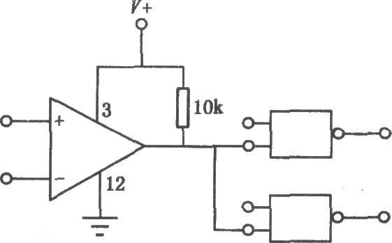
Figure1. independent comparator
Bias current: The input impedance of the ideal comparator is infinite, so theoretically, it has no effect on the input signal, but the input impedance of the actual comparator cannot be infinite. There is a current at the input end that flows through the internal resistance of the signal source and flows into the comparator, which creates an additional pressure difference. The bias current (Ibias) is defined as the median of the input currents of the two comparators and is used to measure the effect of input impedance. The maximum bias current of the MAX917 series of comparators is only 2nA.
Super power swing: In order to further optimize the operating voltage range of the comparator, Maxim uses the parallel structure of the NPN tube and the PNP tube as the input stage of the comparator, so that the input voltage of the comparator can be expanded. The lower limit can be the lowest level, the upper limit is 250mV higher than the power supply voltage, thus reaching the Beyond-theRail standard. The input terminal of this comparator allows a larger common-mode voltage.
Drain-source voltage: the comparator has only two different output states (zero level or power supply voltage), and the output stage of the comparator with full power swing characteristics is an emitter follower. Therefore, there is a very small pressure difference between its input and output signals. The voltage difference depends on the emitter junction voltage under the saturation state of the internal transistor of the comparator, which corresponds to the drain-source voltage of the MOSFFET.
Output delay time: it includes the transmission delay of the signal through the components and the rise time and fall time of the signal. For high-speed comparators, such as MAX961, the typical value of the delay time can reach 4.5ns and the rise time is 2.3ns. When designing, pay attention to the influence of different factors on the delay time, including the influence of temperature, capacitive load, and input overdrive.
Ⅲ Classification
Zero-crossing voltage comparator: A typical amplitude comparison circuit, its circuit diagram, and the transmission characteristic curve are shown in the figure.
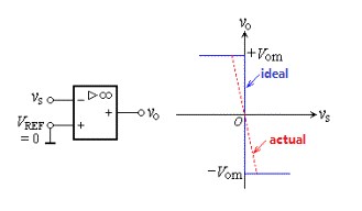
Figure2. Zero-crossing voltage comparator
Voltage comparator: Change an input terminal of the zero-crossing comparator from the ground to a fixed voltage value to get a voltage comparator. Its circuit diagram and transmission characteristic curve are shown in Figure.
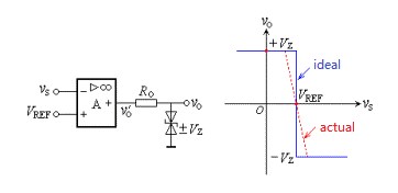
Figure3. fixed voltage comparator
Window comparator: The circuit consists of two amplitude comparators, some diodes, and resistors. The circuit and transmission characteristics are shown in Figure. When the potential level of the high-level signal is higher than a certain specified value VH, it is equivalent to the positive saturation output of the comparator circuit. When the potential level of the low-level signal is lower than a certain specified value VL, it is equivalent to the negative saturation output of the comparator circuit. This comparator has two thresholds, and the transmission characteristic curve is window-shaped, so it is called a window comparator.
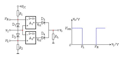
Figure4. window comparator
Hysteresis comparator: A resistor divider branch is drawn from the output to the non-inverting input. The circuit and transmission characteristics are shown in Figure. When the input voltage vI gradually increases from zero and VI is less than VT, the comparator output is a positive saturation voltage, and VT is called the upper threshold (trigger) level. When the input voltage VI>VT', the comparator output is a negative saturation voltage, and VT' is called the lower threshold (trigger) level.
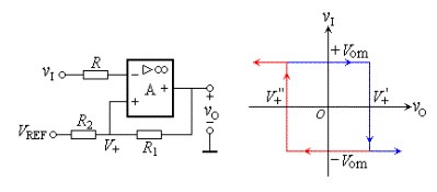
Figure5. hysteresis comparator
Ⅳ Application
Four comparators are used to form a current detection circuit, which can be used to indicate the four states of the input current. The resistor "Shunt" is used to convert the input current into a voltage signal. R1 and R2 are used to set the gain of the operational amplifier and are comparators, providing the required reference voltage. R4 ~ R7 can be used to set the detection thresholds corresponding to different digital output states.
Zero crossing comparator
The zero-crossing comparator is used to detect whether an input value is zero. The principle is to use a comparator to compare two input voltages. One of the two input voltages is the reference voltage Vr and the other is the voltage to be measured Vu. Generally, Vr is connected from the non-inverting input terminal and Vu is connected from the inverting input terminal. According to the result of comparing the input voltage, the forward or reverse saturation voltage is output. When the reference voltage is known, the measurement result of the voltage to be measured can be obtained. When the reference voltage is zero, it is a zero-crossing comparator.
The zero-crossing comparator constructed with the comparator has a certain measurement error. When the product of the voltage difference between the two input terminals and the open-loop amplification is less than the output threshold, the detector will give a zero value. For example, when the open-loop magnification is 106 and the output threshold is 6v, if the voltage difference between the two input stages is less than 6 microvolts, the detector outputs zero. This can also be considered the uncertainty of measurement.
Relaxation oscillator
Comparators can be used to construct relaxation oscillators, where both positive feedback and negative feedback are applied. Positive feedback is a Schmitt trigger, which forms a multivibrator. The RC circuit adds negative feedback to it, which causes the circuit to start to oscillate spontaneously, making the entire circuit from a latch to a relaxation oscillator.
Level shifting uses open-drain comparators (such as LM393, TLV3011, and MAX9028) to construct a level shifter to change the signal voltage. Choosing an appropriate pull-up voltage can flexibly choose the converted voltage value. For example, use the MAX972 comparator to convert ±5V signals into 3V signals.
Analog to digital converter
The function of the comparator is to compare whether an input signal is higher than a given value, so it can convert the input analog signal into a binary digital signal. Almost all digital-to-analog converters, including delta-sigma modulation, contain comparators to quantize the input analog signal.
Ⅴ Voltage comparator
The voltage comparator can be regarded as an operational amplifier with an amplification factor close to "infinity". The function of the voltage comparator is to compare the magnitude of the two voltages (using the high or low level of the output voltage to indicate the relationship between the two input voltages): When the voltage at the "+" input terminal is higher than the "-" input terminal, the voltage comparator output is high level; when the "+" input terminal voltage is lower than the "-" input terminal, the voltage comparator output is low level.
The role of voltage comparator: It can be used as an interface between analog circuits and digital circuits, as well as waveform generation and conversion circuits. A simple voltage comparator can change the sine wave into a square wave or rectangular wave with the same frequency. A simple voltage comparator has a simple structure and high sensitivity, but its anti-interference ability is poor, so people have to improve it. The improved voltage comparators include the hysteresis comparator and window comparator. Operational amplifiers are used to determine "operational parameters" through feedback loops and input loops, such as magnification. The feedback can be part or all of the output current or voltage. The comparator does not need feedback and directly compares the quantities of the two input terminals. If the non-inverting input is greater than the inverted phase, the output is high, otherwise, it outputs low. The input of the voltage comparator is a linear quantity, and the output is a switch (high and low level) quantity. In general applications, linear operational amplifiers can sometimes be used to form voltage comparators without negative feedback.
Chips that can be used as voltage comparators: all operational amplifiers. Common ones are LM324 LM358 uA741 TL081\2\3\4 OP07 OP27, which can be made into voltage comparators (without negative feedback). LM339 and LM393 are professional voltage comparators with the fast switching speed and small delay times. They can be used on special voltage comparison occasions. In fact, they are also an operational amplifier.
 UTMEL
UTMEL
We are the professional distributor of electronic components, providing a large variety of products to save you a lot of time, effort, and cost with our efficient self-customized service. careful order preparation fast delivery service
1.What are comparators used for?
A comparator circuit compares two voltages and outputs either a 1 (the voltage at the plus side; VDD in the illustration) or a 0 (the voltage at the negative side) to indicate which is larger. Comparators are often used, for example, to check whether an input has reached some predetermined value.
2.What are the basic comparators?
A basic op-amp comparator circuit can be used to detect either a positive or a negative-going input voltage depending upon which input of the operational amplifier we connect the fixed reference voltage source and the input voltage too.
3.What is comparators in metrology?
Comparator is a precision instrument • Employed to compare the dimension of given component with given standard • Employed to find out, by how much the dimensions of the given component differ from that of a known datum.
4.How does an lm311 comparator work?
The LM311 is a single comparator. This means it is composed internally of one comparator. It compares these voltage inputs and determines which is the larger value. Based on this, electronic decisions can be made based on which input is greater and which is smaller.
5.What is inside a comparator?
In electronics, a comparator is a device that compares two voltages or currents and outputs a digital signal indicating which is larger. It has two analog input terminals and one binary digital output.
 Discovering New and Advanced Methodology for Determining the Dynamic Characterization of Wide Bandgap DevicesSaumitra Jagdale15 March 20242673
For a long era, silicon has stood out as the primary material for fabricating electronic devices due to its affordability, moderate efficiency, and performance capabilities. Despite its widespread use, silicon faces several limitations that render it unsuitable for applications involving high power and elevated temperatures. As technological advancements continue and the industry demands enhanced efficiency from devices, these limitations become increasingly vivid. In the quest for electronic devices that are more potent, efficient, and compact, wide bandgap materials are emerging as a dominant player. Their superiority over silicon in crucial aspects such as efficiency, higher junction temperatures, power density, thinner drift regions, and faster switching speeds positions them as the preferred materials for the future of power electronics.
Read More A Comprehensive Guide to FPGA Development BoardsUTMEL11 September 202520515
This comprehensive guide will take you on a journey through the fascinating world of FPGA development boards. We’ll explore what they are, how they differ from microcontrollers, and most importantly, how to choose the perfect board for your needs. Whether you’re a seasoned engineer or a curious hobbyist, prepare to unlock new possibilities in hardware design and accelerate your projects. We’ll cover everything from budget-friendly options to specialized boards for image processing, delve into popular learning paths, and even provide insights into essential software like Vivado. By the end of this article, you’ll have a clear roadmap to navigate the FPGA landscape and make informed decisions for your next groundbreaking endeavor.
Read More 800G Optical Transceivers: The Guide for AI Data CentersUTMEL24 December 202510895
The complete guide to 800G Optical Transceiver standards (QSFP-DD vs. OSFP). Overcome supply shortages and scale your AI data center with Utmel Electronic.
Read More The 2026 Engineer’s Guide: Choosing the Right MCU for Your Next IoT & New Energy ProjectUTMEL30 April 2026891
A comprehensive comparison of 2026's leading MCUs from ST, NXP, and Microchip across power efficiency, processing performance, connectivity, and ecosystems to help engineers select the optimal chip for next-gen IoT and new energy projects.
Read More AI Server Components: Engineering Next-Gen Data Center Hardware for 100kW RacksUTMEL15 May 2026429
The transition from traditional enterprise IT to AI-driven workloads has rendered legacy data center hardware obsolete, forcing infrastructure planners to re-engineer server components for extreme thermal environments.
Read More
Subscribe to Utmel !
![ATAES132A-MAHER-T]() ATAES132A-MAHER-T
ATAES132A-MAHER-TMicrochip Technology
![TLE8263EXUMA1]() TLE8263EXUMA1
TLE8263EXUMA1Infineon Technologies
![HCS365/P]() HCS365/P
HCS365/PMicrochip Technology
![HCS200/P]() HCS200/P
HCS200/PMicrochip Technology
![DLPA2005ERSLR]() DLPA2005ERSLR
DLPA2005ERSLRTexas Instruments
![ATSHA204-SH-CZ-T]() ATSHA204-SH-CZ-T
ATSHA204-SH-CZ-TMicrochip Technology
![SN74AVC6T622PWR]() SN74AVC6T622PWR
SN74AVC6T622PWRTexas Instruments
![MOC3061VM]() MOC3061VM
MOC3061VMON Semiconductor
![PAM8904JPR]() PAM8904JPR
PAM8904JPRDiodes Incorporated
![AD9961BCPZRL]() AD9961BCPZRL
AD9961BCPZRLAnalog Devices Inc.


